HVAC Design - Multi-Family Residential
Once you have a load-optimized building design, it is time to decide on the type of HVAC system you want to use to meet these loads. In this design exercise, you will first select an HVAC system type based on resulting carbon emissions, costs and space requirements (Task A). You will then modify the duct geometry and riser position to spatially and aesthetically complement your design (Task B).
Task A: System Selection
In this portion of the exercise, you will evaluate the performance of six different HVAC systems.
You will choose between an all-air system or a system that provides minimum outside air. Your options include:
All-Air: Variable Air Volume (VAV)
Minimum Outside Air: Fan Coil Units with Dedicated Outdoor Air System (DOAS)
You will also select the type of equipment providing hot and chilled water to your building. Your options include:
Natural Gas Boiler and Water-Cooled Chiller
Air Source Heat Pump and Air-Cooled Chiller
Ground Source Heat Pump
See the figure below for schematic diagrams of the 6 different options you will be evaluating.

Figure 1: Diagrams for 6 HVAC system options including central plant equipment.
You first need to set up your thermal model in Grasshopper and then run an energy simulation to compare the systems based on first cost, operating cost, operating carbon, payback period, and space requirements.
To get started, open a Rhino 3D file which includes your thermal zone geometry and template description. Open the HVACer_MultiFamRes.gh grasshopper from the buildVAC GitHub repository (in case you have trouble getting access, reach out to Ali Irani) and follow the instructions in the GH definition, starting at the top left.
Step 1: Define Location
Define your weather file for your project site.
Step 2: Define Geometry And Templates
To get started, select your Apartment and Corridor zone descriptions and save them as a new template in your Rhino file’s ClimateStudio library. Make sure that the fuel costs and carbon emissions in the template have been set correctly. Ensure that your template has a defined value for Fresh Air Per Person and Fresh Air Per Area.

Figure 2: Save the thermal zone description for your building in the Rhino file’s template library
Step 2a: Select the thermal zone BREPs from your Rhino thermal model and select the previously saved zone template for your building. Assign the BREPs for both the Apartment and Corridor zones and assign the respective templates.
Step 2b: Select the window geometry and apply the same glazing type as for your Rhino thermal model.
Step 2c: Select the ground plane (where your building touches the ground) and define the boundary condition.
Step 2d: (optional) Define exterior shading objects such as neighboring buildings or external light shelves.
Step 3: Initiate Energy and Sizing Simulation
Step 3a: Specify a directory on your computer where you would like to save the simulation results. The path name should not include any blanks.
Step 3b: Run simulation
After your energy model has finished running, you should see a detailed energy use breakdown for the 6 HVAC system options along with a series of additional performance metrics for evaluation. Depending on the size of your model, the full simulation may take upwards of 15 minutes. An example output is shown in Figure 3 below. Given the performance metrics from the table, the calculated payback period, as well as your general knowledge of and preference for HVAC systems, indicate which system you will select going forward. Submit a screenshot of your version of Figure 3 and a brief motivation for your system choice. Describe your decision from a utility perspective (natural gas vs. electricity) and take some time to list the pros and cons for systems you did not select.


Figure 3: Example energy use predictions for 6 different HVAC systems for a multi-family residential building in Boston.
Task B: Spatial Design
In this portion of the exercise, you will design the spatial layout of your selected HVAC system. Follow the steps below to modify the geometry of the HVAC system based on spatial and aesthetic considerations.
Step 1: HVAC Spatial Layout
Step 1a: For all Corridor zones, draw one or more polylines on the ceiling/roof of the zone corresponding to the main supply duct location. Each floor should have at least one corridor centerline. Draw the polylines in Rhino and reference them in Grasshopper. Do not use closed polylines.
Step 1b: Draw and select riser points on the roof of your building. You need a minimum of one riser. Draw the points in Rhino and reference them in Grasshopper.
Step 1c: Select your desired HVAC system from the dropdown list. This should be the system you selected in Task A.
Step 1d: Select the desired aspect ratio for your ductwork.
Step 1e: Modify the placement and geometry of the main ductwork vertically. Duct height is measured from the floor.
A summary of the various geometric parameters is provided in the GH script. Consider placing risers near core locations or toward the back of of the building and route the primary supply air ducts through circulation areas.
Once you have completed your initial design in Grasshopper, bake the various elements in Rhino. You can access the different geometries using the various Preview components in the script (Figure 4). Right-click on each component and then bake the corresponding geometry to a Rhino layer.

Once the duct geometry has been converted into Rhino geometry, you can modify it in order to, for example, edit zone branch placements, etc. or resolve any geometric conflicts or placement issues. When you have completed your design, please provide a an axonometric perspective and representative section of your final design (Figure 5). Please also submit the Rhino geometry (.3dm file) and Grasshopper script (.gh file) to CANVAS. Please comment on any challenges you faced in the final duct placement, all special considerations, or any other HVAC related decisions you made at this stage.
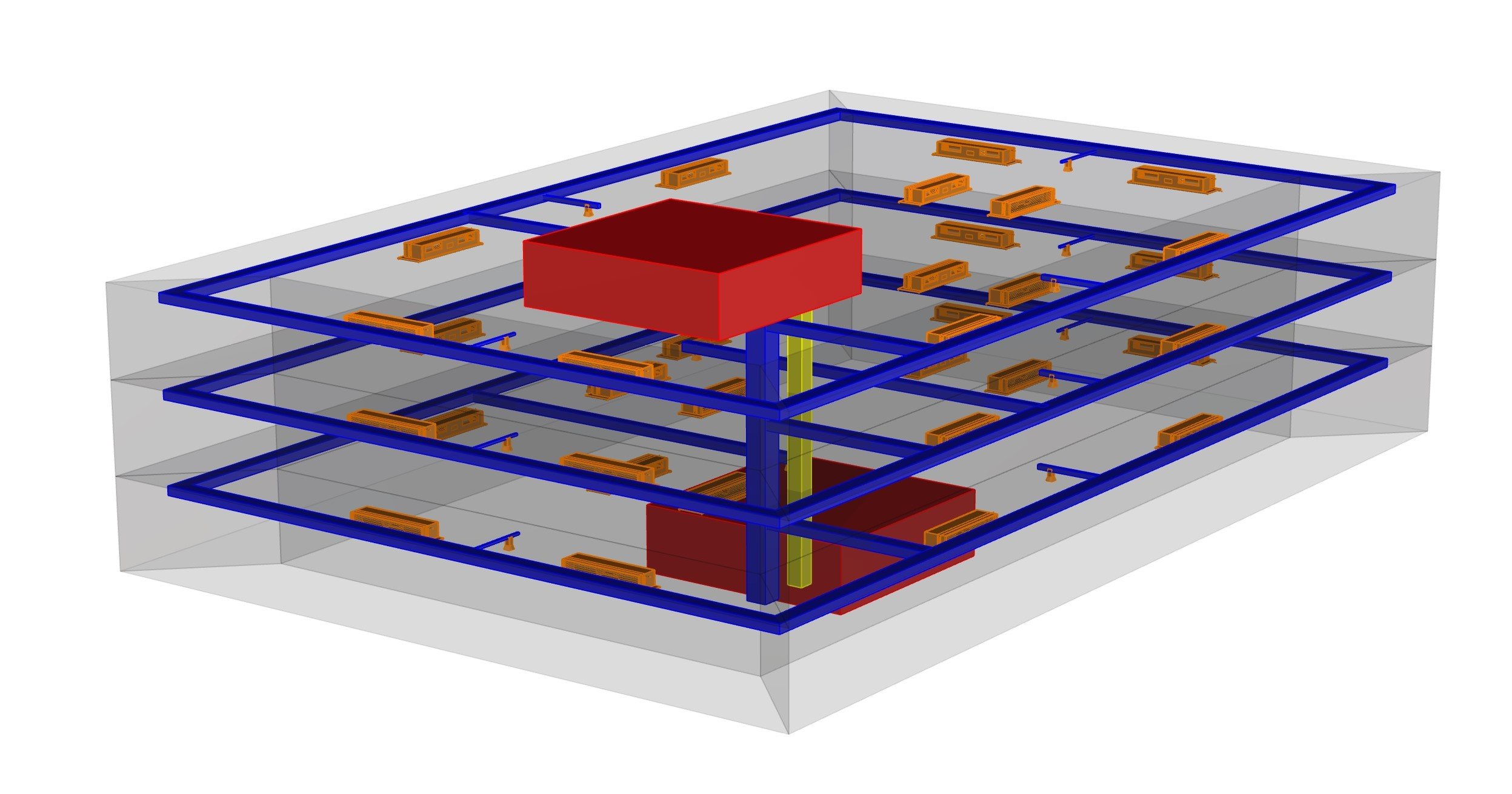

Figure 4: The script allows for visualizing energy model geometry as well as HVAC system ductwork, equipment, and spaces.
Figure 5: Representative axonometric perspective and section drawing showing risers, main branch duct and terminal equipment as well as fan rooms and basement mechanical rooms.
Related Video Tutorial/Handbook Chapter
MIT SDL buildVAC GitHub repository